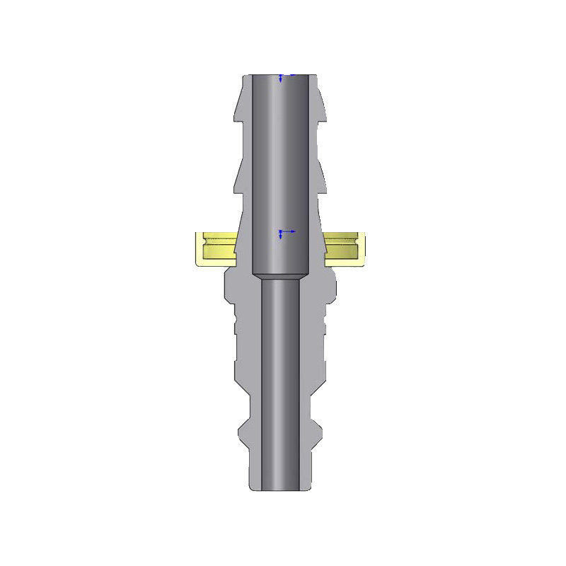
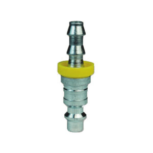
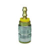
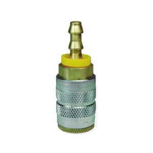
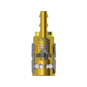
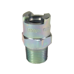
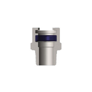
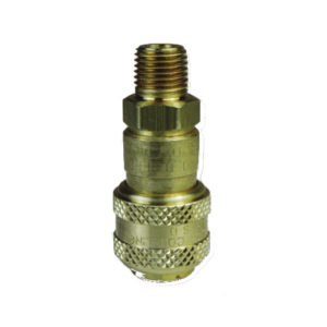
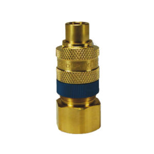
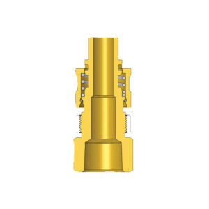
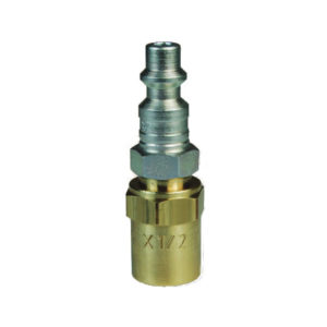
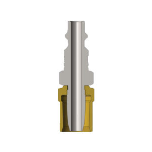
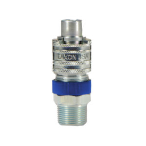
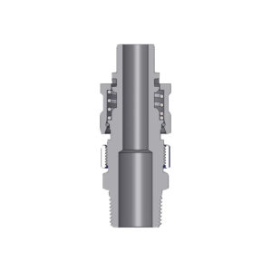
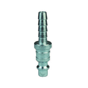
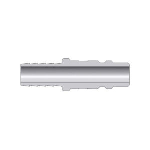
DF-Series Industrial Interchange Nipple (Push-Loc Barb)
RM8.00 – RM88.00
| SPECIFICATIONS | • Rated pressure when connected with Brass D-Series Automatic Couplers: 500 PSI (35 bar) Maximum Working and 16,000 PSI (1,100 bar) Burst • Rated pressure when connected with Brass F-Series Manual Couplers: 500 PSI (35 bar) Maximum Working and 11,500 PSI (790 bar) Burst • Rated pressure when connected with Steel F-Series Manual Couplers: 500 PSI (35 bar) Maximum Working and 6,500 PSI (448 bar) Burst |
| CONSTUCTION | • Machined components are manufactured using solid bar stock. • Steel componentry is plated using ROHS Compliant Trivalent Chrome. |
| COMPATIBILITY & INTERCHANGE DATA |
• Foster 3, 4, 5 and 6 Series • Parker 30- Series Automatic Interchange & Parker 20-Series Manual Interchange • Hansen 3000, 4000, 5000 and 6000 & Hansen 1000, 400 and 500 |
| HOW IT WORKS | • To disconnect, begin by holding the hose on the nipple side with three of your fingers, leaving your thumb and index finger free. • Grab the sleeve with your thumb and index finger and begin to pull the sleeve towards the palm of your hand. • After pulling the sleeve, the nipple will move out of the coupler slightly. Continue to hold the hose and coupler sleeve until all air is fully exhausted. • After the line is fully exhausted, you are able to safely separate the nipple from the coupler. |
| SIZE | PART NUMBER | HOSE ID | MATERIAL | LENGTH | Maximum OD | HEX Inch | Weight Lb | ||
| inch | mm | inch | mm | ||||||
| 1/4″ | D2B2 | 1/4″ | Steel | 2.09 | 53.1 | 0.69 | 17.5 | – | 0.04 |
| 1/4″ | D2B2-B | 1/4″ | Brass | 2.09 | 53.1 | 0.69 | 17.5 | – | 0.04 |
| 1/4″ | D2B3 | 3/8″ | Steel | 2.09 | 53.1 | 0.86 | 21.8 | – | 0.05
|
| 3/8″ | D3B2 | 1/4″ | Steel | 2.21 | 56.1 | 0.75 | 19.1 | – | 0.06 |
| 3/8″ | D3B3 | 3/8″ | Steel | 2.21 | 56.1 | 0.75 | 19.1 | – | 0.07 |
| 3/8″ | D3B4 | 1/2” | Steel | 2.35 | 59.7 | 0.75 | 19.1 | – | 0.09 |
| 1/2″ | D4B4 | 1/2” | Steel | 2.67 | 67.8 | 0.75 | 19.1 | – | 0.11 |
| 3/4″ | D6B6 | 3/4” | Steel | 2.99 | 75.9 | 1.00 | 25.4 | – | 0.23 |
*It is important to be safe when installing quick disconnect couplings into a pneumatic circuit. Never install a pneumatic coupling directly into an air tool, use a piece of hose that is at least 18″ long, between the tool and the coupling, to prevent damage to the coupling. To protect the operator, safety devices, such as a safety check valve and safety cable should be installed in case there is a hose or coupling failure.
* Operating pressure for couplings utilizing hose barb connections may be dramatically reduced to that of the hose rating and/or hose end connection combination.
Consult hose manufacturer’s catalog for hose end connection ratings. If in doubt, test under controlled conditions for suitability to application.
* Dixon cannot assume liability for misapplication of production resulting in equipment down-time, lost production, and/or personal injury including death.
WARNING: Cancer and Reproductive Harm
| Weight | 1 kg |
|---|---|
| Size | 1/4", 3/8", 1/2", 3/4" |
| Part Number | D2B2, D2B2-B, D2B3, D3B2, D3B3, D3B4, D4B4, D6B6 |
| Material | Steel, Brass |
Be the first to review “DF-Series Industrial Interchange Nipple (Push-Loc Barb)” Cancel reply
You must be logged in to post a review.


Reviews
There are no reviews yet.